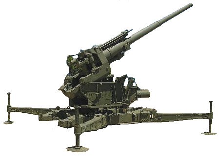
After studying a number of gun designs, in 1928 the RA Committee suggested a 3.7 inch Anti-Aircraft Gun, firing a 25 lb shell to a ceiling of 28,000 feet would fill the gap between the existing 3 inch gun and the 4.7 inch then under development. A specification was issued in 1933 for a 3.7 inch gun weighing 8 tons, capable of being towed at 25 mph and brought into action in 15 minutes. Designs were put forward in 1934 and the Vickers design accepted. Production was authorised in April 1937 and the first guns delivered in January 1938.
The carriage was complicated and it weighed well over the specified 8 tons so, at first, people preferred the 3 inch for being lighter and handier. Its vastly superior performance soon changed peoples minds and by mid war it was being acclaimed as one of the best guns of its type in existence.
It was contiually improved, the most important advance being the Molins Fuze Setter No. 11. This was a combined fuze setter and loading mechanism. The fuse setter descended on the shell, set the fuze and withdrew. The tray swung over to the breech and the round was rammed. The breech closed, tray retracted and the gun fired. The whole operation from putting the shell in the tray and hitting the switch was entirly automatic. This not only took strain off the crew and speeded up the process it also produced a fixed time between fuze setting and firing which aided more accurate prediction of the target.
In January 1941, the War Office demanded a new design with a ceiling of 50,000 feet and a time of flight to that height of 30 seconds. They also required the ability to fire 3 rounds with a fourth loaded in 20 seconds. The proposals for this new design were based around the Naval 5.25 inch gun and the existing 4.5 inch gun. They were the 5.25 as it stood or lined down to 4.5 or lined down to 3.7 and the 4.5 lined down to 3.7. The 5.25 inch was chosen as the long term solution but the 4.5 lined down to 3.7 inch was adopted as a stop gap until sufficient 5.25 inch guns were available.
To deal with the high velocity required, a new rifling was introduced. Known as RD (Research Department) Rifling it worked with a specially designed shell. Rifling started at zero with the lands rising to full height just over 4 inches from the start of rifling. At the muzzle end the grooves gradually reduced until at 11 inches from the muzzle the gun had become a smoothbore. The shell had a driving band and twin centring bands at the shoulder. These spread the stress of the shell spinning, evenly along its length. As the depth of rifling decreased, the copper bands were squeezed into canelures in the body. Instead of protruding into the airstream and degrading the flight, these bands were now smooth with the shell body, improving airflow and maintaining velocity.
This gun was introduced in 1943 as the Mark 6. It had a 65 calibre 3.7 inch liner in the jacket of a 4.5 inch Mark 2 gun on a 4.5 inch static mounting. Although only a stop gap, it performed so well it remained in service until 1959.
Gun
| Mark 1 1937 | Loose barrel liner in full length jacket & Mk1 breech mechanism |
| Mark 1/1 1948 | Mk1 modified by radiussing rear corners of breech block mortise |
| Mark 2 1937 | Loose barrel in short jacket. Mk1 or Mk2 barrel and breech |
| C Mark 2 1944 | Canadian made Mk2 |
| Mark 2A 1945 | Change to breech ring and block to fit Mountings 2B or 3A |
| Mark 2/2 1948 | Conversion of Mk2 by radiussing breech ring mortise |
| Mark 2/3 1948 | Conversion of Mk2A as for Mk2/2 |
| Mark 2/4 1951 | Conversion of Mk2/2 or 2/3 for elecric firing gear on Mk4 mountings |
| Mark 3 1938 | Mk1 gun with Mk2 breech. Made in limited numbers |
| Mark 3/1 1948 | Conversion of Mk3 by radiussing breech ring mortise |
| Mark 3/2 1947 | Conversion of Mk3 for use with Mk3A or C3A mounting |
| Mark 3/3 1947 | Conversion of Mk3/1 as for Mk3/2 |
| Mark 3/4 1951 | Conversion of Mk3/1 or 3/2 as for Mk2/4 |
| Mark 4 1943 | Experimental 3.7 loose liner in 4 inch Mk5** gun body. 3 made, cancelled |
| Mark 5 1943 | Experimental 65 calibre 3.7 inch loose liner with orthodox rifling in the 4.5 inch Mk2 gun body. Abandoned in favour of Mk6 design |
| Mark 6 1943 | 65 calibre 3.7 inch loose liner with RD Rifling in 4.5 inch Mk2 gun body |
| Mark 7 1943 | Mk2 gun with simplified breech mechanism. Only a few experimental guns made |
Mountings
| Mark 1 | Mobile, original design. Magslip data dials & rocking bar open sights. Gunlayers faced forward. Gun trunnioned at rear with spring balancing gear. Loading tray removed in 1942 & replaced when Molins MFS No.11 fuze setter fitted |
| Mark 1A | As Mk1 but without rocking bar open sights |
| Mark 2 | Static mounting. Fitted with counterbalancing weight instead of spring balancing gear. Magslip & rocking bar sights, layers faced rear. Fixed to Holdfast AA Mounting No.2 |
| Mark 2A | Mk2 fitted with R37 remote power control |
| Mark 2B | Mk2 fitted with MFS No.11 & automatic loading gear |
| Mark 2C | Mk2 with R37 RPC 7 MFS No.11 |
| Mark 3 | Wartime production, mobile. Similar to Mk1 but layers faced rear |
| Mark 3A | Mk3 with MFS No.11 |
| Mark C3 | Canadian made Mk3. Carriage, wheels & brakes differed from British version |
| Mark 4 | 4.5 inch Mk1 mounting modified for 3.7 inch Mk6 |
| Mark 4/1 | Mk4 with MFS No.12 & automatic loading gear |
Crew
Originally 10 this was later reduced to 7 as loading and fuze setting became automatic.
| No. 1 | Gun Commander |
| No. 2 | Layer for Line |
| No. 3 | Layer for Elevation |
| No. 4 | Fuze Dial number |
| No.5 | Breech Operator |
| No. 6 | Rammer |
| No. 7 | Loader |
| No. 8 | Loader |
| No.9 | Fuze Setter Operator |
| No. 10 | Ammunition number |
Data
3.7 inch Gun Mks 1-3
| Weight of Gun & Breech Mechanism | 3,931 lbs |
| Total Length | 195.15 inches |
| Length of Bore | 185 inches (50 calibres) |
| Rifling | 28 grooves, uniform right hand 1/30 |
| Breech Mechanism | Horizontal sliding block, semi-automatic, percussion fired |
| Elevation | -5° to +80° |
| Traverse | 360° |
| Recoil System | Hydropneumatic, constant 32 inches on mobile mounting. Hydro-spring, constant 18 inches on static mounting |
| Weight in Action | 20,541 lbs mobile; 23,100 lbs static |
| Rate of Fire | Hand loading 10 rounds per minute Auto-loading 25 rounds per minute |
3.7 inch Gun Mk 6
| Weight of Gun & Breech Mechanism | 6,552 lbs |
| Total Length | 252 inches |
| Length of Bore | 240.5 inches (65 calibres) |
| Rifling | 28 grooves, uniform right hand 1/27, RD system |
| Breech Mechanism | Horizontal sliding block, semi-automatic, percussion fired |
| Elevation | 0° to +80° |
| Traverse | 360° |
| Recoil System | Hydropneumatic, constant 18 inches |
| Weight in Action | 38,360 lbs |
| Rate of Fire | Hand loading 8 rounds per minute Auto-loading 19 rounds per minute |
Performance
3.7 inch Gun Mks 1-3 firing standard 28 lb HE Shell
| Muzzle Velocity | 2,600 feet/second |
| Maximum Horizontal Range | 20,600 yards |
| Maximum Ceiling | 41,000 feet |
| Effective Ceiling | Varied with fuze, Predictor & method of fire control 32,000 feet with Predictor No.10 & Fuze Time No. 208 |
Ammunition
| Shell, HE, Mark 1C | Used Fuze, Time 119 or 223 earlyn on, then Mechanical Time Fuze 207, 208 or 214 |
| Shell, Shrapnel, Mark 2C | For use against low flying aircraft. Used Fuze Time No. 199 |
| Shot , AP, Mark 5T | Solid steel shot with a tracer. Penetration of 117mm/1,000 yards/30° |
| Propelling Charge | Full Charge – standard charge Reduced Charge – training and ground role use Burst-short Charge – practice against live targets. Follows the same flight path as Full charge but bursts well short of the target for safety |
3.7 inch Gun Mk 6 firing standard 28 lb HE Shell
| Muzzle Velocity | 3,425 feet/second |
| 25,600 yards | |
| 59,300 feet | |
| Effective Ceiling | 45,000 feet with Predictor No.10 & Fuze Time No. 208 |
Ammunition
| Shell, HE, Mark 4C | Similar to Mk1C above but with forward centering bands & wider driving band. Used with Time Fuze 218 |
| Propelling Charge | Only the Full Charge was provided |